Fender Panel Design
Fender panels are critical to the correct performance of the fender system. It’s used to distribute the reaction forces to the hull of berthing vessels. Many factors should be considered for the design calculation, such as hull pressure and tidal range, steel grade, bending, service life and so on.
Recommended minimum thickness for steel in fender panels are:
* Plates exposed on two surfaces: 12mm
* Plates exposed on one surface: 9~10mm
* Internal mernbers (not exposed): 8mm
Hull Pressure
Hull pressure vary greatly with the class and size ship. PIANC gives the following advice on hull pressure:

Hull pressures are calculated using the frontal panel area(excluding lead-in chamfers) as follows:
ΣR: Combined Reaction Forces of all rubber fenders
A1: Valid Panel Width excluding lead-in chamfers(m)
B1: Valid Panel Height excluding lead-in chamfers(m)
PP: Permissible hull pressure(N/m2, psi)
Approximate Hull Pressure for other fender types:
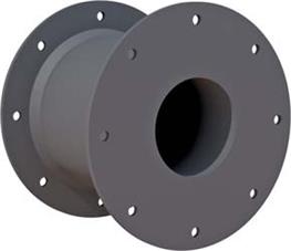
The above formula and table apply to berths fitted with frontal panel systems. However, many berths use Cylindrical and Arch fenders safely and without damaging the ship's hull, despite the fact that these fenders exert higher hull pressures. The Arch Fenders have hull pressures of 760~1300kN/m2. Cylindrical Fenders have 460~780kN/m2. Also bear in mind that when cylindrical fenders are used with large chains or bar fixings through the central bore, the hull pressure will be higher to approximately double the above figures. Again there is no evidence to show that this causes hull damage.
Recommended minimum thickness for steel in fender panels are:
* Plates exposed on two surfaces: 12mm
* Plates exposed on one surface: 9~10mm
* Internal mernbers (not exposed): 8mm
Hull Pressure
Hull pressure vary greatly with the class and size ship. PIANC gives the following advice on hull pressure:

|
Hull Pressure Guide |
|
|
Type of Vessel |
Hull Pressure |
|
Conteriner vessels 1st and 2nd generation |
< 400 |
|
3rd generation (Panamax) |
< 300 |
|
4th generation |
< 250 |
|
5th and 6th generation (Superpost Panamax) |
< 200 |
|
General Carge Vessels |
|
|
≤ 20,000 DWT |
400~700 |
|
> 20,000 DWT 40 |
< 400 |
|
Oil Tankers |
|
|
≤ 60,000 DWT |
< 300 |
|
> 60,000 DWT 40 |
< 350 |
|
VLCC |
|
|
Gas Carriers (LNG/LPG) |
< 200 |
|
Bulk Carriers |
< 200 |
|
SWTH |
Belted |
|
RO-RO Vessels |
|
|
Passenger Vessels |
|
Hull pressures are calculated using the frontal panel area(excluding lead-in chamfers) as follows:
P=ΣR / A1xB1 ≤ PP
Where
ΣR: Combined Reaction Forces of all rubber fenders
A1: Valid Panel Width excluding lead-in chamfers(m)
B1: Valid Panel Height excluding lead-in chamfers(m)
PP: Permissible hull pressure(N/m2, psi)
Approximate Hull Pressure for other fender types:
The above formula and table apply to berths fitted with frontal panel systems. However, many berths use Cylindrical and Arch fenders safely and without damaging the ship's hull, despite the fact that these fenders exert higher hull pressures. The Arch Fenders have hull pressures of 760~1300kN/m2. Cylindrical Fenders have 460~780kN/m2. Also bear in mind that when cylindrical fenders are used with large chains or bar fixings through the central bore, the hull pressure will be higher to approximately double the above figures. Again there is no evidence to show that this causes hull damage.
Product Categories
Contact Info
E-mail: info@dolphinmarines.com
Tel: 00852-29738324
Fax: 00852-21159613

 info@dolphinmarines.com

